Oct 19 2006 Install the AC wiring to the charger or inverter including an AC grounding conductor of a size equal to the current carrying conductors unless the circuit exceeds 30A in which case the grounding conductor may be one size smaller E11161382. DC is for Priorities AC is for.
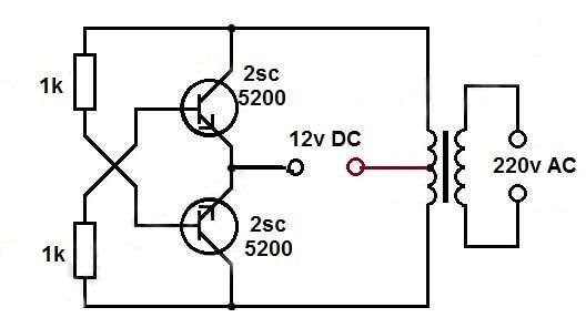
 12 V To 220 V 2 Ampere Inverter Circuit Circuit Diagram Circuit Electronics Circuit
Negative of the charge controller.

Wiring diagram inverter dc to ac. It is not a problem if you dont need 240 Volts which you probably dont. How to make dc to ac 1500Watt inverter circuit homemade project Parts List. Sep 01 2016 3000 Watt Inverter Circuit Diagram.
Standard North American AC power is 240 Volt split-phase meaning there is a center tap which provides neutral for 120 VAC on either side. Apr 13 2020 One powers the Air Conditioning and the other goes to the Xantrex Freedom 20. Shore by providing a multi-stage charging profile adapted to the battery type AGM Lithium etc.
There are several possible ways to wire your inverter. But in any case you need to ensure that you dont have either shore power or generator power connected to the output of the inverter. In many ductless split DC inverter design the indoor fan used is DC fan instead of AC fan.
In simple words an inverter is used to provide alternating current AC from the direct current sources ie batteries and so on. Below is a RV Electric Wiring Diagram or schematic including the converter and inverter for a generic RV. Converts DC to AC.
The AC Connecting the inverter to the RV electrical system side of the RV inverter install can get more complicated. So Inverter is a circuit or you can call a device which converts DC to AC. ConnectingHard-wiring inverter to AC Panel offgrid Welcome to the forum.
DC load is also connected to the DC output terminal of the charge controller. Similarly the outdoor fan used is DC fan instead of the conventional AC fan. Converts AC to DC.
Planning on having one 50A 120V three wire plug and a Victron Galvanic Isolator. Editor Elcircuit Published Thursday September 01 2016. An inverter can be used to operate electronic devices such as kitchen appliances TVs computers power tools and so on.
Convert 120V AC to 12V DC to power the 12V appliances directly. This inverter circuit diagram which can change the voltage 12 Volt DC to 230 Volt AC. Scheme inverter circuit is capable of removing power output up to 3000 Watt for beginners as possible to assemble a circuit schematic This inverter will be a little complicated and confused.
Convert power from 12V DC from the battery bank to 120V AC allowing to use common household appliances. Provided that there is a sufficient source of electricity converters and inverters give an RV the flexibility to power all of its devices regardless of the power source AC or DC. Mosfet 23N50E x 4 ic KA3525 x 1 ic IR2110 x 2 Diode UF4007 or FR107 x 6 electro.
In essence 120 VAC inverters just put out half of this. The single shore power line would feed to the Multiplus then split with one circuit to the Air Conditioner would disconnect if shore power is lost and the other to the AC panel. Aug 07 2013 Wiring the Inverter.
60 rows Sep 06 2020 This becomes the main breaker for the pre-inverter 120 volt AC. In this article I have tried to explain the full details about the Installation of Inverter at our Home with Wiring Diagram. The following solar panel wiring diagram shows that an 120W 12V solar panel is directly connected to the 12V charge controller.
The inverter in our house is a device which takes 12V DC supply and gives 230V AC Supply. If you are thinking why to use solar inverter instead of the normal electric one then it is because the solar one makes use of the solar energy which is available in abundant from the Sun and is clean and pollution free. Feb 25 2010 A power inverter is simply an electrical device that converts direct current or DC to alternating current or AC.
Types of RV Electricity There are 2 main types of sources of RV electricity within your RV 12 Volt DC and 120 Volt AC same as 110 volt - just like your stick. Brick for our purposes. Charge the battery bank from a 120V source aka.
When purchasing your unit check with the personnel whether the compressor and fans used are DC type before making a decision of buying the air conditioner or heatpump. Mar 15 2020 As you know some devices require AC and some require DC. Sep 08 2020 The Inverter takes the 12V DC power stored in the batteries and converts it to 120V AC power to power the 120V AC items around the camper.
Battery and inverter are connected to the battery terminals Positive. Replacing Stock Camper Batteries with Busbars A positive and negative busbar take the place of the stock batteries in the stock battery location assuming that upgrading batteries means you will not be able to store your new battery. Aug 14 2015 A solar inverter helps devices that run on DC power to run in AC power so that the user makes use of the AC power.
 Dc To Ac Inverter With The 555 Electronics Mini Projects Electronic Circuit Design Electronics Circuit
 Simple Transformer Electronic Circuit Projects Circuit Diagram Circuit
 Welcome This Is A Simple 24v Dc To Ac Inverter Circuit Diagram By Freeborn Emm Circuit Diagram Electrical Circuit Diagram Diagram
 How To Make 12v Dc To 220v Ac Converter Inverter Circuit Design Electrical Circuit Diagram Circuit Diagram Circuit Design
 How To Make Simple Dc To Ac Inverter Circuit Diagram Diy Electrical Electronic Parts
 1 5v Dc To 220v Ac Converter Electronic Circuit Projects Circuit Diagram Circuit Projects
 12v To 220v Inverter Circuit Diagram Circuit Diagram Electronics Circuit Electrical Circuit Diagram
 12v Dc To 220v Ac Inverter Circuit Electronics Circuit Circuit Diagram Circuit
 Cd4017 100 Watt Inverter 12dc To 220ac Circuit Diagram Circuit Electronics Circuit
 Simple Pure Sine Wave Inverter Circuit 500 Watt Pure Sine Circuit Diagram True Sine Wave Inverter Circuit Diagram Circuit Diagram Sine Wave Pure Products
 3000 Watt Power Inverter 12v Dc To 230v Ac Electronic Circuit Projects Electronics Circuit Power Inverter
 A Relatively Simple 1000 Watt Pure Sine Wave Inverter Circuit Is Explained Here As Can Be Seen In Electronic Circuit Projects Circuit Diagram Circuit Projects
 Inverter Electrical Circuit Diagram Circuit Diagram Electronic Schematics
 Simple Dc To Ac Transformer Inverter 1 7v Dc To 58v Ac Youtube Electronic Circuit Design Circuit Design Transformers
 Dc To Ac Inverter With Ic555 Electronic Engineering Electronic Schematics Electronics Basics
 Circuit Diagram Of Solar Inverter For Home How Solar Inverter Works Solar Inverter Circuit Diagram Solar Charger
 The Proposed 3v To 110v 0r 220v Circuit Listed Below Is Actually A Dc To Dc Converter Electronics Circuit Electronic Circuit Design Electronic Circuit Projects
 1kva 1000 Watts Pure Sine Wave Inverter Circuit Elec Eng World Electronic Circuit Projects Circuit Diagram Circuit Projects
 Dc To Dc Ac Inverter Circuit Diagram Circuit Diagram Diagram Circuit
 Pin On Electronics
 Inverter Circuit Diagram 5000w Agendadepaznarino Com Circuit Diagram Electronic Circuit Projects Circuit Projects
 Inverter Project 12v Dc To 120v Ac Circuit Diagram Electronic Schematics Circuit
 In This Post We Can Learn How To Make Inverter 12v Dc To 220v Ac Making Circuit Diagram Electronic Circuit Design Circuit Diagram Electrical Circuit Diagram
 Transformerless Dc To Ac Inverter Circuit Diagram Templates Agendadepaznarino Com Circuit Projects Electrical Circuit Diagram Circuit
 This 6v To 220v Inverter Circuit Schematic Is One Of The Voltage Inverter Circuit Starting From 6 Vol Circuit Diagram Power Supply Circuit Electronics Circuit
 How To Make 12v Dc To 220v Ac Converter Inverter Circuit Design Circuit Design Electronic Circuit Projects Circuit Diagram
 Make A 5000watt Inverter 12 220v With Tl494 And Power Mosfets Youtube Electronic Circuit Design Circuit Diagram Electrical Circuit Diagram
 7 Modified Sine Wave Inverter Circuits Explored 100w To 3kva Homemade Circuit Projects Sine Wave Circuit Projects Electronic Circuit Projects
 12vdc 220vac Inverter Jpg 628 350 Circuit Diagram Electronic Circuit Design Electronics Basics
 Pin On Powers
 Pin On Faruk
 12v Dc To 220v 50 Hz About 500w Power Output Low Cost To Built This Inverter Circuit Circuit Diagram Electronics Circuit Electronic Schematics
 Here Is A Simple 12 Volts Dc To Ac Inverter Circuit This 120v Ac Power Source Is Built W Electronic Schematics Electronic Circuit Projects Electronics Circuit
 12v至230v使用脉宽调制器ic Sg3525的变换器电路原理图 Circuit Diagram Circuit Circuit Components
 Pin On 1
 Homemade 2000w Power Inverter With Circuit Diagrams Gohz Com Circuit Diagram Diagram Power Inverter
 Let S Try To Work Out The Proposed 500va Pure Sine Wave Inverter Circuit Layout Elaborately With Th Electronic Circuit Projects Sine Wave Electronic Schematics
 How To Make Inverter 12v Dc To 220v Ac Making Circuit Diagram And Making Transformer Elec Electronic Circuit Design Electrical Circuit Diagram Circuit Diagram
 Simple Low Power Inverter Circuit 12v Dc To 230v Or 110v Ac Diagram Using Cd4047 And Irfz44 Power Mo Circuit Diagram Basic Electronic Circuits Power Inverter
1
 Pin On Audio
 Converter 12 Vdc To 230 Vac Or Inverter Circuit Diagram Circuit Diagram Electronic Engineering Electrical Engineering Projects
 Inverter Circuit 12vdc To 220v 50hz 500w Circuit Diagram Electronic Schematics Electronics Circuit
A Relatively Simple 1000 Watt Pure Sine Wave Inverter Circuit Is Explained Here Using A Signal Amp Electronic Circuit Projects Circuit Diagram Circuit Projects
 How To Make A Simple 200 Va Homemade Power Inverter Circuit Square Wave Concept Electronic Circuit Projects Circuit Projects Circuit Diagram
 38 Pure Sine Wave Inverter Circuit Diagram Pdf Ohio In 2021 Circuit Diagram Electronic Schematics Sine Wave
 Pin On Electronics Circuits Chips
