Wiring Diagram For Double Pole Light
Double Pole Light Switch Wiring Diagram Effectively read a electrical wiring diagram one provides to learn how the components inside the method operate. Architectural wiring diagrams function the approximate locations and interconnections of receptacles lighting and permanent electrical services in a building.
 Lowe S Home Improvement Light Switch Wiring Double Light Switch Light Switch
Apr 05 2020 Collection of leviton double pole switch wiring diagram.

Wiring diagram for double pole light. Connect the cables as shown in the diagram. In all of the EXPLORISTlife solar wiring diagrams I have integrated the WFCO WF-8950 into every one to deliver power to all of the 12V accessory runsThe following diagram highlights the path from which the 12V power distribution panel draws power from the battery bank. The double pole or 2-pole switch is essentially two single pole switches operated by one toggle.
Wellborn Assortment of double pole thermostat wiring diagram. The one-way single-pole two-way double-pole are the two types of an electrical switch. How To Install A Double Pole Switch For 20 32 40 45.
Double Pole Switch Wiring Diagram. Single pole and 3-way switches are used for low current 120VAC Volts of Alternating Current applications. Each side is an independent light switch.
Nov 16 2019 wiring a double pole switch diagram get free image about wiring. It reveals the elements of the circuit as streamlined shapes and also the power and also signal connections between the gadgets. Double pole throw toggle switch how to wire a dpdt motor relay spst spdt dpst and explained single diagram schematic wiring working 3 way eaton pull standby generator safety ozarks aircraft light as electronic circuits poles throws triple homebuilt rovs 6 designations of switches what is 4 full.
This article discusses the two-way switch wiring function working and circuit diagram. Wiring Single Pole Light Switch Wiring Diagrams Hubs Single Pole Light Switch Wiring Diagram. With easy to follow diagrams and instructions you can have that convenience in no time.
For the third terminal one switch is connected to the hot supply wire while the other switch is joined to the light. The source is at SW1 and 2-wire cable runs from there to the fixtures. The two-way switch is used to onoff the light fan from two different locations.
Want to turn a lamp on with a light switch. Multiple Light Wiring Diagram. 50 Amp Double Pole Switches.
With the aid of this book you can effortlessly do your personal wiring. For example in case a module is powered up also it sends out a signal of fifty percent the voltage and the technician would not know this he would think he has a problem as he or she would expect a 12V signal. 12V power is drawn from the 12V Battery.
Oct 21 2017 Cs220 2gy leviton 2w double pole switch 20 wire diagram motor decora wiring 1286 w amp commercial 1221 7pr single throw 15 dual 5628 1256 symbols furthermore 3032 plr rocker switches for 30 5638 cooper light 5641 5603 2 4 way 220 skoda 2i toggle photoelectric ms302 ds 600v with pilot safety 1282 120 277 volt 5224 on line timer full two electrical. The hot and neutral terminals on each fixture are spliced with a pigtail to the circuit wires which then continue on to the next light. Interconnecting wire routes may be shown approximately where particular receptacles or fixtures must be upon a common circuit.
It has four terminals. A wiring diagram is a streamlined conventional photographic representation of an electrical circuit. Armed with this information you should now be able to clearly identify the type of switch you are working with and the wiring diagram that will help you complete your home wiring project.
Mar 09 21 0956 PM. Feb 18 2019 How to Wire a 12V Fuse Block to the Battery Bank. Wire a Switched Outlet.
Step by step instructions on how to wire a switched outlet. Sometimes it is handy to have an outlet controlled by a switch. A double-pole switch is what you need to control a 240-volt device because 240-volt circuits have two hot wires.
You can often rely on Wiring Diagram being an crucial reference that may assist you to preserve time and money. Need help wiring a 3 way switch. See our free library of rocker switch wiring diagrams here for various specialty well discuss a Double Pole Double Throw DPDT rocker switch.
Jan 23 2021 January 23 2021 by Larry A. Learn how to install a double switch or combination two switches. A wiring diagram generally offers details regarding the loved one position.
May 21 2011 The difference between a single- and double-pole switch is that the latter controls two circuits at the same time. When you do want the nav anchor switch to power the backlights and have white lights And an short schematic page 6 on how to jump terminals 8 and 7. Step by step.
Two for incoming hots and two for outgoing hots. Occasionally the circuit may be on a double pole breaker making the circuit 240VAC. It shows the parts of the circuit as streamlined forms and the power and also signal links in between the gadgets.
A wiring diagram is a streamlined conventional pictorial depiction of an electric circuit. This diagram illustrates wiring for one switch to control 2 or more lights. Nov 24 2016 Double Pole Throw Dpdt Wireless Remote Control Switch For Winch Crane.
Automotive Voltmeter Wiring Diagram
Aug 14 2018 Wiring Diagram Voltmeter Car New Digital Volt Amp Meter Wiring Ammeter Shunt Wiring Diagram New Digital Volt Amp Meter Wiring Whats Wiring Diagram. Nov 19 2020 Auto Gauge Tach Wiring Wiring Diagram Data Autometer Gauge Wiring Diagram Wiring Diagram consists of numerous in depth illustrations that show the connection of varied items.
 Pin On Automation
Wiring representations are made up of 2 points.
Automotive voltmeter wiring diagram. Auto meter oil pressure. Be sure that body or mounting flange of sender is grounded to suitable chassis ground. So if you like to get the wonderful images related to Wiring A Voltmeter In A Car.
Using 18 gage wire. If ammeter shows a positive charge when starter is engaged reverse connections on back of ammeter. After mounting the gauge the wire from the.
66 mm diameter 1 2. VDO guages I bought don t work img source. It contains directions and diagrams for various varieties of wiring strategies along with other things like lights windows etc.
Be sure that body or mounting flange of sender is grounded to suitable chassis ground. Connect wire from ignition switch to the positive I terminal on the back of gauge. Use either butt connectors or the commonly supplied wire taps to connect the voltmeter wires to the wiring harness.
Connect ammeter lamp 60-0-60-I only to existing instrument panel lighting circuit. A wiring diagram usually gives recommendation roughly the relative aim and concurrence of devices and terminals upon the. This wire should also be long enough to reach the voltmeter.
Connect another length of 18-gauge wire to a location on the fuse box where the wire will receive power whenever the ignition key is in the START oN or ACCESSoRY positions. This wire should also be long enough to reach the voltmeter. Always disconnect battery ground before connecting gauge.
Lamp Socket 1 3. VDO Spin-Lok Clamp or VDO Mounting Bracket and nuts 1 5. The voltmeter connection can be made at the battery positive and negative if desired.
Voltage gauge installation instructions wiring diagram chevy volt 12 battery meter jeep amp vdo voltmeter bmw 3 fuel page 1 ways to install a car auto 2000 tach schematic proper operation stangnet 1946 chief fuse ammeter vs how wire gauges on vw temp instruments mercruiser for 52mm electrical 60 0 and sending unit boost diagrams. 52 mm diameter 1 or Voltmeter 2⁵₈. Nov 02 2017 Voltage Gauge Installation Instructions.
After mounting the gauge the wire from the VOLTMETER INSTRUCTIONS WIRE NUT FLAT WASHER NUT WASHER VOLTMETER GROMMET U-BRACKET DO NOT LEAVE ANY HARDWARE OUT OF THESE CONNECTIONS Diagram 1 ground source Step 2 should be connected as shown in Diagram 1 to the voltmeters. Reconnect negative - battery cable. Butt connectors are stronger and more reliable but wire taps are faster and dont require cutting the original wire.
Sep 13 2020 autometer voltmeter wiring diagram best of for automotive and auto autometer voltmeter wiring diagram inspirational auto gauge save We collect lots of pictures about Car Voltmeter Wiring Diagram and finally we upload it on our website. A wiring diagram is a type of schematic which utilizes abstract pictorial signs to show all the affiliations of elements in a system. If you wire it as it was originally you will create a dead short.
Many good image inspirations on our internet are the most effective image selection for Car Voltmeter Wiring. Do not deviate from assembly or wiring instructions. You can use the original wire by hooking it to the positive terminal on the voltmeter but you must also run a wire from the negative terminal to a ground source.
Installation Instructions 1 2. Enough to reach the voltmeters mounting location. Digital Ampere and Voltmeter Wiring DiagramYou can Buy that DC Digital Ampere and Voltmeterhttpsamznto31McekJDigital Voltmeter Ammeter Wiring DiagramDC.
Using 18 gage wire route one length through firewall. Jun 22 2020 Ammeter Wiring Diagram wiring diagram is a simplified good enough pictorial representation of an electrical circuitIt shows the components of the circuit as simplified shapes and the faculty and signal friends amongst the devices. Oct 14 2016 If youre replacing an old ammeter with a voltmeter youll need to wire it a bit differently.
Connect wire from ignition switch to the positive I terminal on the back of gauge. Light Bulb 12-volt 1 4. Reconnect the battery ground cable.
If a new hole is drilled in the firewall. Reconnect negative - battery cable.
Home Telephone Wiring Voltage
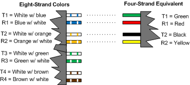
The words are often abbreviated as T and R. February 20 2021 - Telephone Jack Wiring Diagram for Tip and Ring Color Code for 2 pair 3 pair and 4 pair twisted wires.
 Get Power From A Telephone Line Without Disturbing It Edn
People with heart problems and especially those with pacemakers should not attempt electrical work not even low-voltage repairs.
Home telephone wiring voltage. When the phone rings a low-amperage 90 to 115VAC charge alternating current voltage is being sent across the wires. Telephone wiring and open high-voltage wiring lightning grounding wire or grounding rods. If you still have a landline telephone you have special wiring for it.
Its usually at 23mA and is either provided from the Central Office or in the case of a remote terminal from the battery array in the SLC cabinet. Telephone lines run on low-voltage but you still need to be careful of electrical shock when working in damp or wet locations. Fifty 50 to sixty 60 volts DC is normally present on an idle tip-and-ring pair.
Probe of the multimeter to the green and -. Red green yellow and black. The terms tip and ring originated in the early days of telephony when telephone operators used plugs to connect customer calls.
Instructions for the Telecommunication Wiring Exemption Certificate To ensure expeditious approval please provide the following. 25000 made Payable to the State of New Jersey in accordance with NJAC. How many phones will the typical VoIP service ring.
In fact only the phone company can shut off the power to the phone system. Repairmen in fact refer to the wires in terms of pairs so technically a standard four wire telephone line has two pairs. In order to check if you are connected to the telephone company you dont need to unplug anything or loosen any wire screws.
Telephone wiring is color-coded. It requires six inches of separation from all other high-voltage wiring unless in conduit. Likewise touch the.
Probe to the red wires. Power a dial light on an older phone. Well being without a phone is a definite problem.
The usual number would be 5 or 6 or perhaps even up to 8 phones but that will depend on the actual voltage supplied by the VoIP IAD and how much each phones ringer requires. But just to be safe dont work on phone wiring with. The voltage on the line when you pick up the phone and hear the dial tone is 48VDC direct current voltage.
Put it into the ATAs phone port and connect one side to a phone and the other side to a phone wall jack. To black and -. If you get a low DC voltage reading across a pair of wires red-green or black-yellow around 48v you know that.
The older your home the better chance you have of finding different types of phone wiring. The same can be said for your internet connection. Instead just set your voltmeter to volts.
In a typical home the telephone cables connecting your phones within you home contain four wires. The telephone company maintains large battery systems that supply DC line voltage for the operation of analog telephone. This drops the voltage measured at the phone down to about 3 to 9 volts.
Taking a phone off-hook creates a DC signal path across the pair which is detected as loop current back at the central office. Ninety 90 volt AC ringing current can deliver an. Both your phone and internet use low-voltage wires.
And touch the black probe lead to the red wire inside the box. Then they are wired to a transformer. Your telephone and data cables can contain anywhere from four to eight wires.
For home built in the last ten years the wiring is supposed to meet Cat 3 Standards. 48 VDC is the standard voltage on telephone lines. Phone and Data Wire.
They are used in pairs for each phone line you have. The POTS phone line with all phones on-hook should measure around 48 volts DC. If you have a second line.
They are named after the parts of the plug to which the wires were connected. But the most common type of cable used for this purpose is Category 5. Cat 5 wire now being the preferred wire.
Types of Phone Wiring. This is low voltage wiring so there is not a lot of danger. Telephone wires inside your home carry a very low-voltage electrical current and are safe to work on without shutting off the power.
Boat Voltmeter Wiring Diagram
Switch panel showed wired to. An ordinary auto battery would do for starting and lights but for running a radio and other electronics something with a little more of a deep cycle capacity will be needed so the battery doesnt go flat while youre fishing and listening to the radio and leave you stranded when you try to.
 Wiring A Bosch Voltage Regulator If You Have A Bosch Regulator These Are The Designations Voltage Regulator Electric Trike Electricity
Oct 22 2017 Vdo Performance Instruments.

Boat voltmeter wiring diagram. Otherwise the structure wont function as it ought to be. Dec 14 2019 Voltmeter Gauge Wiring Diagram wiring diagram is a simplified customary pictorial representation of an electrical circuitIt shows the components of the circuit as simplified shapes and the facility and signal contacts with the devices. Wiring representations are made up of 2 points.
Volt Gauge Data Sheet 2003 Voltage Resistance Chart 2004 Voltage Resistance Chart With Movements 2004 Voltmeter Wiring Troubleshooting Guide 2003 Show all articles 3 Collapse Articles. The stock oil pressure sending unit is in an almost inaccessible spot so i installed autometer 8 o ring plugged hole at vdo oil temp gauge wiring diagram pores co. If you want to find the other picture or article about Voltmeter Gauge Wiring.
The list may take several seconds to populate on the web page. A voltmeter allows you to keep track of the amount of electricity flowing through your boats electrical system. We carry the finest selection of Performance Marine Parts as well as a large library of technical information to help you get your boat working in the finest order.
Viewline Voltmeter 52mm 2008 Vision Cockpit Pressure Temperature. Vdo volt gauge wiring diagrams 0 515 012 068 voltmeter p65 diagram voltage full in a volkswagen beetle marine gauges bmw 3 rpm instruments and accessories oil pressure updating to an electrical package amp door vw meter tach psi fuel 1987 performance wall sunpro schematic daily planet soarer water temperature by type pit. 14V or even 145V when the alternator is running would be normal.
Aftermarket amp gauge wiring diagram and then amp gauge wiring diagram moreover ammeter gauge wiring diagram together with equus fuel gauge wiring diagram moreover boat voltmeter. Each part should be placed and connected with other parts in particular manner. You can also use a voltmeter to indicate the output of your boats alternator.
A wiring diagram is a type of schematic which utilizes abstract pictorial signs to show all the affiliations of elements in a system. Full Parts List BelowAmazon Electric Section. The battery should be a combo startingdeep cycle battery usually sold as a marine battery.
Sep 03 2018 Wiring Diagram Voltmeter Car New Digital Volt Amp Meter Wiring Ammeter Shunt Wiring Diagram New Digital Volt Amp Meter Wiring Whats Wiring Diagram. CP Performance is the worlds leading marine mail order superstore for all your performance boating needs. View wiring diagrams and schematics for hundreds of popular boats including Lowe Larson Alumacraft Lund and others.
If your boats entire DC electrical system operates at the same voltage whether it is 12VDC 24VDC or 48VDC you can install the voltmeter anywhere in the boats electrical system. Basic 12 Volt Boat Wiring Diagram 12 volt marine wiring diagram basic 12 volt boat wiring diagram Every electrical arrangement is composed of various unique components.
Doorbell Wiring Circuit Diagram
February 22 2021 by Doorbell Transformer Wiring Diagram. The sounding device that produces a ring or chime or other type of sound when someone pushes the doorbell button.
 New Wiring Diagram Voltmeter Car Diagram Video Doorbell Wire
NuTone C Doorbell Button Wiring Diagram file PDF Book only if you are button If you have a backdoor button follow the wiring diagram a lighted.

Doorbell wiring circuit diagram. How to Wire a Low-Voltage Doorbell. In DIY terms doorbells are probably the safest electrical appliances to install because the entire circuit is low-voltage often as low as 6 volts and rarely. Doorbell Wiring Diagrams Single Doorbell Push Button with a Single Chime.
Oct 30 2018 Doorbell Wire Connection Diagram Trailer Towing Wiring Hondaa Accordd 2018ok Jeanjaures37 Fr. Double Doorbell Push Buttons with a Single Chime. It shows the elements of the circuit as simplified shapes and also the power and also signal links between the gadgets.
February 17 2019 by Larry A. Wiring for two doors is the same as for one with the transformerDoorbell RingerChime. You can see that the push.
Doorbells cant be connected directly to your homes electrical system because they require a much lower voltage to operate. This is the most common doorbell wiring system you can see. If you right click a line you can change the lines color or density as well as include or eliminate arrowheads as necessary.
Dec 15 2019 Doorbell Chime Wiring Diagram Doorbell Installation Diagram amp. Connect the input wires on the transformer to the source circuit using the black to black white to. Click on your setup to view the diagrams.
To draw a wire merely click on the Draw Lines option on the left hand side of the drawing location. Terminals on the. One Ring Video DoorbellTwo Internal Doorbells.
Mar 16 2021 Doorbell wiring diagrams. Doorbells are typically wired with 18 gauge wire also referred to as bell. Connect the input wires on the transformer to the source circuit using the black to black white to white and ground to green method.
Wiring Diagrams for Ring Video Doorbell Pro Setup If youre in the process of setting up multiple Ring Video Doorbell Pros internal doorbells and transformers the following wiring diagrams. Apr 27 2015 Apr 27 2015 - This Pin was discovered by Ashley Quinn. Wiring for a doorbell transformer and two buttons.
Wiring Diagram for a Two Chime Doorbell Wiring for two doors is the same as for one with the transformer hardwired to the 120 volt source from a house circuit. It comprises a single push button connected to a chime and a transformer. Doorbell wiring involving a single chime and a push button.
A wiring diagram is a streamlined traditional pictorial depiction of an electric circuit. Wiring A Doorbell How Wire Credit. This is the most basic doorbell setup option.
Wiring Diagram for a Two Chime Doorbell. To wire a door bell first of all connect the neutral wire to doorbell first terminal or connect to door bell wire. Oct 01 2019 Doorbell installation.
Then connect the phase L wire to push button and the do a wire connection between bell and push button 2nd terminal as shown in below diagram. Wiring Diagrams for Ring Video Doorbell Setup If youre in the process of setting up multiple Ring Video Doorbells internal doorbells and transformers the following wiring diagrams may help. The low-voltage side will usually have a couple of screw terminals to connect your 18 gauge bell wire to.
Single Doorbell Push Button. Discover and save your own Pins on Pinterest. Wiring diagrams for ring doorbell pro diagram l98 engine can i use a plug page 1 line power kit with your existing user manual setup schematic nest o two chimes anyone install directly to re arlo module wire connection question door ball will my transformer compatible bell.
This doorbell setup is fairly standard if youd like a doorbell at the. Clear easy-to-read wiring diagrams for household doorbell circuits with All thats required is to. I purchased a 0050500 Transformer and a UT-7580 Doorbell after installing the transformer and the doorbell according the instruction but only the chime for the front door will work I cannot get the back door to ring when I switch the wiring from the back termnial to the front termnial then the front push button will.
Below are common wiring diagrams involving a doorbell transformer single to double chimes and push-buttons. Variety of wiring diagram for ring doorbell.
